ECCC 2011 Recap

As usual, ECCC 2011 was both hectic and fun. It’s been a few days since the show, as it took a while to travel home and recover.

RETRO Innovations arrived Friday evening in time to unload equipment into the show hall and select a couple choice tables near power and good traffic areas.  However, almost as soon as we finished, it was time to close the hall for the night.  I gathered up a few items and set up in the Fairfield Hotel foyer to finish some soldering and check on email.  When I left at 1AM (early, I know), the room was still full of Commodore folks.

Saturday started strong, with sales brisk until nearly noon.  ZoomFloppies sold well, though uIEC/SD unit sales were nontrivial as well (typically, a large number of the same folks attend each year, so year over years sales of the same item tend to decrease after the first year).  JiffyDOS ROM sets sold at a steady pace, as did IEC cables.  By mid afternoon, sales had tapered off and I was able to present ZoomFLoppy at 4PM in the demo area without too much trouble.  I drug in an 8050 drive to show off IEEE support, recently added to the ZF firmware, while showing the rest of the ZoomFloppy features.

In the evening, I worked with Leif Bloomquist on a long-in-development VIC-MIDI project.  Having first collaborated with Leif on the project in early 2010, it’s been a long road getting to this point.  But, Leif worked on the driver code in the evening and was able to coax correct operation out the circuit before nightfall.  Hopefully, a finished design and a product offering will be available before the first show in 2012.

After the hall closed Saturday night, we once again gathered in the hotel foyer.  I sat with Six and Elwix of Style to discuss some new hardware design ideas, but mainly just enjoyed the din of activity.

This year, the show opened again on Sunday, though I had already made alternate Sunday plans.  Though I was in no hurry, packing went slower than expected since I had to pull items out a number of times to make last minute sales.  I can’t complain about sales, though.  By 1PM, I had stuffed everything back into containers and closed up shop.

Of course, no show would be complete unless purchases were made.  While eyeing some individual 8″ floppy disks, I happened upon a VIC-1540 with an original DOS ROM.  Those ended up in my possession (I already have a 1540, but I don’t have an original ROM). Anticipating purchases, I had left a bit of room for things like this and the 10 VIC expansion cases (Think VIC-1020, but minus the expansion PCB.  They were used to lock down the VIC in an education setting) Leif brought to the show (I purchased them at WoC 2010, but was not in attendance). As well, I asked Six (Oliver Viebrooks) to bring an SX64 shipping box to that show I had stashed at his home years before.  Finally, the shipping box would make it home.

Or not…  At the end of the show, I ended up purchasing a Xerox Phaser 8400 Workgroup color printer (I’ve been looking for a color unit for invoice printing, but couldn’t justify the cost of a new color laser in lieu of the perfectly functioning LaserJet 5 currently in use).  The price was too good to pass up, but the cargo area could not hold the printer, the products, the VIC cases, and the SX64 shipping box in addition to suitcases.  So, the SX box went home to downstate IL with family.  Maybe one day it’ll make it home.  It’s been in IL, then in KY, and now somewhere else in IL.

To be truthful, I attend to see folks and share stories, not sell products.  It was nice to catch up with folks from past events as well as meet people I’ve only known online.  Still, it is nice to sell enough stuff to finance the trip.

Above all, I’m exceedingly grateful that Jason Compton underwrites the entire cost of the event, offering it for free to businesses and attendees alike.  May it continue to be held for years to come.  I’m also excited that the Vintage Computer Festival was held at the same time in the same building.  Though I didn’t get to spend much time at their exhibits, the exhibits were well planned and very intriguing.

ZoomFloppy Tape Support

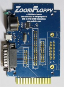
Arnd Menge has delivered the first set of patches allowing ZoomFloppy to interface with 1530/1531 tape hardware.  In the coming days, Arnd hopes to complete development of this new feature, and I am looking into creating a daughtercard that will attach to the ZoomFloppy via the X5 expansion connector.

Obviously, such support is alpha at present, but the device is proving very versatile with the recent improvements!

Arnd Menge

uIEC/SD 3.2 vs uIEC/SD 3.1

uIEC/SD 3.2 versus 3.1

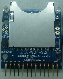
Even though there’s not much to tell, some folks asked about the differences in the new v3.2 uIEC/SD design.  A picture is worth its weight in gold here, but I’ll also point out some less apparent details.

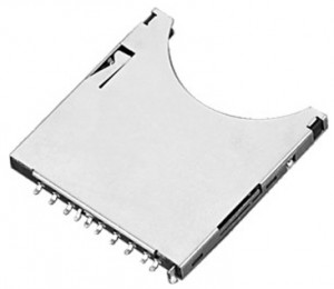
  • Due to the new SD socket footprint, I was able to push the edge of the socket further from the edge of the board.  This should help with implementations sitting behind thick plastic cases.
  • Two small half moons (on the top left and bottom right) should allow the unit to be mounted in a Hammond 1551RBK enclosure.
  • Although not populated on the PCB, there are pads for a Dallas DS1307 (or compatible) RTC with battery backup.  The battery pins are shown on the right of the new PCB, while you can make out the watch crystal footprint below them on the right side.
  • The LEDs have been pushed further outside the PCB.  Truly, the assembly house went overboard on the first batch, but they should stick out to the edge of the SD socket.

Nothing else, I am afraid.  I tried to add device jumpers to the design, but ran out of space and time to route the pads.  The rest remains the sames, including:

  • Pinout.  v3.2 shares the same pinout as v3.1 and v3.0
  • Mounting location.  The mounting holes are in exactly the same place.  Though the SD socket has mover 1/8″ further out, the PCB will fit in exactly the same place as previous designs.
  • Same uC.  The Atmel ATMEGA1281 is still in use, as is the 74LVC06  serial bus driver


How Low Can You Go?

Advanced Interconnect Header

Designing “piggyback” PCBs can prove challenging at times.  For example, extending a piggyback PCB outside of the original ICs footprint must contend with physical obstructions (connectors beside the IC, passives like capacitors or resistors sticking out of the original PCB, etc.).  Luckily, it’s often easy to print out a 1:1 version of the design on paper, cut to dimensions, and test fit onto the original board.  Often, obstructions can be mitigated by switching to SMT components and using a smaller footprint or changing the PCB outline to for around obstacles.

However, less easy to design around are height issues. The best approach involves replacing the original ICs function entirely.  Replacement solutions like ROM-el rise little further than the original IC they replace.  If the original IC is still needed, but a pass-through of all signals to the original IC is acceptable, the design can utilize a socket both to contain the original IC, and let the pins from the socket function as the header for the piggyback PCB connector to the original socket.  This solution typically rises a bit further, but rarely far enough to cause issues.

Designing a piggyback PCB that requires the original IC and must reroute some of the original IC signals forms the worst case.  If the original IC height is defined as ‘X’, and we ignore the .8mm to 1.6mm of the PCB, this design still requires a header (‘X’ height), a socket for the original IC (‘X’ height), and the original IC (‘X’ height).

Mind you, most 70’s and 80’s systems designs left lots of room between board or above the original PCB.  Thus, 3X height, while potentially looking out of place, will often continue to work.  However, as designs became more compact, such luxuries are often unavailable.

The Commodore 1541II disk drive PCB is one such example of the last case.  Commodore, in order to reduce overall drive height as much as possible, left little room between the control PCB and the drive mechanism mounted immediately above it.  Designing a piggyback board for use in this device is particularly challenging, as there is simply no way to add any height; the drive mechanism won’t rotate the disk if the piggyback board touches it, and you simply cannot relocate the mechanism.

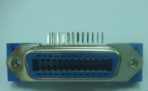
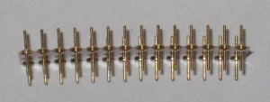
Months ago, I pulled a CMD JiffyDOS ROM out of a 1541II, and was surprised to see an unusual header being used to minimize height.  Instead of a normal header, which is simply a batch of double ended pins stuck in a plastic socket, this header used a thin flexible “film” to hold the pins in place, adding no height at all.  I had no idea of the source, but a quick request on the CBM Hackers mailing list yielded a source.  Vanessa Ezekowitz tracked down the manufacturer (Advanced Interconnections) and the product (Peel-a-Way Removable Carriers).

Of course, this doesn’t solve every problem, but it does offer new hope for designs in height constrained locations.  The solution is not cheap (10X the price of a normal IC header), but it can turn an impossible design into a possible product.
 

uIEC/SD v3.2 Shipping

uIEC/SD Daughtercard v3

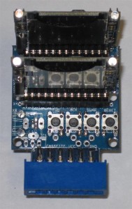
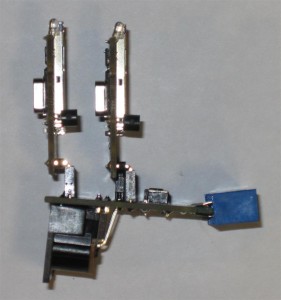
As of tonight, the last of the uIEC/SD pre-orders have finally shipped.  In fact, for the first time since early May, we are caught up on order fulfillment.  Now, I can relate some features of the new uIEC/SD daughtercard option:

  • Two (2) IEC connectors.  No need to ensure the uIEC is the last item on the bus
  • 3 uIEC/SD connectors (one populated by default).  One is designed to point backwards from the daughtercard (for a horizontal setup), while the other two are vertical.  (This means users can reposition the unit for ease of use, or can utilize more than 1 uIEC on the same daughtercard)
  • Integrated power plug.  No more pigtail wire to break.
  • RESET button on board.
  • Selectable uIEC/SD RESET operation.  Removing the on-board jumper will prevent computer resets from affecting uIEC/SD unit.

    uIEC/SD Daughtercard v3 (side view)
    uIEC/SD Daughtercard v3 (side view)


Of course, the original Daughtercard remains available for those who prefer a minimal approach.  The original daughtercard works best for C128D/DCR users, while the new unit works best for other machines.

The new unit will be available as an option in the store shortly.


Finally! uIEC/SD Units Shipping from Manufacturer

uIEC/SD 3.2 Production Unit

After what seems like an eternity, the first 50 uIEC/SD units have been shipped from the assembly house.  Exhibiting the longest design/manufacturing cycle I’ve ever witnessed, they’ve been unavailable since late April, 2011.

For those new to the saga, the normal stock re-order process in early May ran aground when the specified SD socket was unavailable for purchase.  Though the socket had been discontinued (and the manufacturer did send me an email), the sales distributor showed (and allowed me to order) a last batch of units.  I had no idea the distributor would be overcommitted and call notifying me they could not fulfill the order.  That call set off a multi-week effort to find alternate stock, which then morphed into finding another option that fit the footprint, and finally resulted in redesigning the board to accommodate a new SD socket option.  That delay ate up the entire month of May and part of June.

Things started getting interesting in late June, as I awaited new stock.  First, the date slipped, which was not altogether surprising (it was but an estimate at best).  Then, the assembly house sent word the DIN6 IEC connectors would not fit in the daughtercard footprint.  This was not a showstopper, as I had sourced connectors for another project that would work.  A while later, the assembly house IMed on a Thursday night that the new SD connector would not fit the design.  I double-checked the PCB design and measured the sample units.  Everything looked correct.  I asked for a picture to view the issue. They promised one later that day.  But, they are a half day ahead.  I received it the end of their day, Friday morning here in the US.  By that time, they had gone home for the weekend.  Looking at the picture, I immediately solved the problem.  They were trying to solder the old SD socket onto the new PCB design.  Still, that wasted time.

Luckily, after nearly suffering heart stoppage over the SD socket issue, the rest of assembly went relatively smoothly.  Complicating the shipment: most pre-orders specified a daughtercard option.  Thus, both items required assembly before any orders could be filled.  As well, I produced the new daughtercard design in this order.

Now, to see if my design skills are good enough to overcome the lack of prototype assembly and testing.

ZoomFloppy SRQ Nibbling Support

During ZoomFloppy development, Nate Lawson tested and found that the 1571 drive, with it’s faster clock speed and hardware shift register data transfer support, could potentially support serial data nibbling.  Current nibbling options require a cumbersome and difficult-to-install parallel cable.  As attention was placed elsewhere, the idea was shelved pending initial implementation code.

A while back, Arnd Menge submitted a patch to enable serial nibbling using the ZoomFloppy hardware and the 1571 SRQ line.  Continued testing and refinement of the patch goes well.  Thanks go out to Arnd for the patch and bug fixes, and to Nate Lawson for debugging this new functionality.  Currently, only reads are supported, but write support will be added once the basic concept and initial implementation is proven.

When complete and added to the base firmware and OpenCBM libraries and tools, C128DCR 1571CR owners, who previously were unable to utilize their drive for data nibbling (lack of parallel port option) can utilize this solution to quickly read data from the 1571 drive unit.

We’ll continue to monitor the progress of this new feature.  Though the solution is close at hand, software support for this new feature might take longer.


Continued uIEC/SD Delays

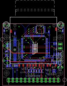
uIEC/SD 3.2 PCB Design

My plan to ship uIEC/SD units by end of June was evidently overly optimistic.  It took longer than expected to modify the uIEC/SD PCB design, and the design had to be checked more thoroughly since I will not have time to assemble and test a sample before ordering the SMT stencil (a metal “mask” laid over the PCB that is used to force solder paste to only deposit on the exposed PCB pads)  and a production PCB run.  Thus, I am crossing my fingers that the redesign is correct.  The new design looks very similar to the older, though I have designed the PCB to fit a small Hammond 1551 enclosure (the 2 half-present holes on the corners of the board).

At this point, I’ve moved the expected ship date to July 12, and alerted customers about the delay.

ZoomFloppy IEEE-488 Support

Thanks to the hard work of Thomas Winkler, ZoomFloppy now supports Commodore IEEE-488 devices.  Many thanks also to Nate Lawson for incorporating Thomas’ changes into the ZoomFloppy base firmware image.

Existing units require a firmware update and the population of the IEEE-488 connector fr operation.  As there is not a simple firmware update utility at present, users may wish to wait until an official upgrade solution is available.  However, users who wish to download some programming SW and follow a step by step tutorial can upgrade immediately (disclaimer:  RETRO Innovations takes no responsibility for upgrade issues, though there is no way to completely brick the unit.  At worst, RETRO Innovations can reprogram the unit and ship back to the customer).  All newly ordered units will contain the updated firmware.