Introduction
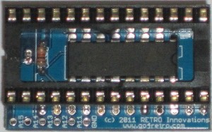
Perfect for the do-it-yourself vintage system enthusiast, the 23XX Adapter converts JEDEC standard 28 pin EPROM, EEPROM, or FLASH ROMs to a 2316,2332, or 2364 socket. Since 23XX ROMs could be produced with active-high or active-low select lines, The 23XX adapter can be configured for either signal level on any applicable select line. The optional 5 highest address lines are available via pads complete with provision for pullup resistors (4.7K).
Options
The 23XX Adapter can be purchased as a bare PCB or a fully assembled unit, configured for 2364 active low select operation.
Requirements
This adapter can emulate various 24 pin mark-programmed ROMs or EPROMs, such as 2316, 2716, 2332, ,2732, and 2364. Other combinations may also be possible.
Purchase
23XX Adapters can be purchased in the RETRO Innovations Online Store.
Technical Details
The onboard 74hct138 3-to-8 decoder converts any combination of the 3 possible chip select lines into a single JEDEC standard select line. If a select line is not needed, that input can be tied to ground via SMT pads on the bottom of the PCB.
Construction Details
Parts needed:
- 1 24 pin .6″ DIP header
- 1 28 pin .6″ DIP socket
- 5 4.7-10K 1/8W resistors
- 1 74hct138
The 74hct138 should be installed first, followed by the resistors, then the socket, and lastly the header.
Support
Configuration
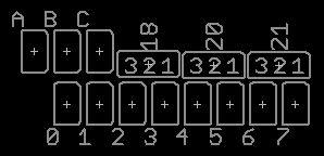
The adapter optionally connects 23XX pins 18, 20, and 21 to a 74hct138 3-to-8 decoder’s A, B, C inputs (18 goes to input A, 20 to B, and 21 to C). Unused ‘138 inputs are driven to ground.
- If pin 18 is used as a select, pads 2-3 shown under the legend ’18’ are connected.
- If not, pads 1-2 on ’18’ are connected, and pad A is connected.
- If pin 20 is used as a select, pads 2-3 shown under the legend ’20’ are connected.
- If not, pads 1-2 on ’20’ are connected, and pad B is connected.
- If pin 21 is used as a select, pads 2-3 shown under the legend ’21’ are connected.
- If not, pads 1-2 on ’21’ are connected, and pad B is connected.
- Then, a truth table is created for A,B,C to show which output pin should be used. For example, if A is connected, B is not, C is connected, and 20 is connected between 2-3, it means ‘000 ‘or ‘010’ are valid inputs. If pin 20 is active low, pin ‘0’ should be connected. If pin 20 is active high, pin ‘2’ should be connected.
Below are some configurations for frequently seen ICs:
| IC | Notes | A | B | C | 18 | 20 | 21 | 0 | 1 | 2 | 3 | 4 | 5 | 6 | 7 |
|---|---|---|---|---|---|---|---|---|---|---|---|---|---|---|---|
| 2316 | !CS1,!CS2,CS3 | 2-3 | 2-3 | 2-3 | X | ||||||||||
| 2716 | !EP,!G,Vpp | 2-3 | 2-3 | 2-3 | X | ||||||||||
| 2332 | !CE1,CE2 | X | 1-2 | 2-3 | 2-3 | X | |||||||||
| 2364 | !CE1 | X | X | 1-2 | 2-3 | 1-2 | X | ||||||||
| 2364 | !CE1 (Alternative, no ‘138 needed) | 1-2 | 1-2 | 1-2 | |||||||||||
| 2364 | CE1 | X | X | 1-2 | 2-3 | 1-2 | X |
Legend:
- ‘X’ means the pads should be soldered together
- ‘1-2’ and ‘2-3’ means the respective pads should be soldered together
Operation
- Remove 23XX IC under test
- Configure 23XX adapter for specific IC chip select usage.
- Install suitable EPROM, FLASH, or EEPROM device with suitable contents into 23XX Adapter socket
- Install 23XX Adapter in circuit under test
- Apply power to circuit
Project Files
EAGLE v7+ schematic and EAGLE v7+ PCB design files are available in the github.com repository.

