Now that we’ve learned a bit about how the 6809E wants to be treated during a direct memory access (DMA) request, we can put all we’ve learned into action. But, before we launch into the details, let’s address some questions that arose during previous article discussions:
Some asked why the logic doesn’t just watch for M6809E signals BA and BS to both equal 1 (this condition indicates that the CPU is halted), commencing DMA actions at that point. This is my fault. As I started the project effort, I didn’t make it clear that I am trying to determine what DMA capabilities exist at the external side of the TANDY Color Computer expansion port (game cartridge port). I did comment about the expansion port initially, but I should have called that out in more detail. It’s worthwhile to also answer how one enables DMA when inside the computer, but that effort requires modifying the internals of the machine (at least plugging and unplugging ICs, which might not be socketed), and thus trades design complexity for end user complexity. The lowest entry point for DMA exploration (as with most things) is the expansion port, so I’ve concentrated my efforts there. But, for the record, we now know that an internal DMA engine need only pull HALT low, watch for BA=BS=1, and then transfer data as desired.
Others asked if halting the CPU and performing data transfers can really be called “DMA”. Instead of just answering the question by articulating the literal definition of DMA, I believe the question speaks more about how the term “DMA” has evolved over the years. In the beginning, DMA actions made no promises about CPU activity. The act of offloading memory access from the CPU and the act of running the CPU while that alternative access occurred were completely different efforts. In fact, Motorola manufactured and sold a DMA controller IC (the 6844 DMAC) that performed DMA actions by stopping the CPU (in various ways). That said, in today’s IBM PC-based world, where the memory bus, the peripheral bus, and the CPU bus are all separated and tied together with “bridge” ICs, it’s expected that a DMA action will not impact CPU operations. That’s the question being asked. I still believe the answer is “yes”, not only because of the literal definition but also that period-correct implementations would have stopped the CPU. But, I will agree that performing data transfers while not impacting CPU performance would be ideal. The conversation did bring up some neat ideas on how one might share the memory bus, not stop the CPU and perform DMA activities, which we can consider in later installments.
Concerning our primary objective, we now know how to safely stop the CPU and gain control of the bus, and we also know how to manipulate the bus to transfer data from one place to another. But, transferring a single piece of data is boring, so let’s add some more value. On the Color Computer 1 and 2, a fully expanded machine would include 64kB of RAM. Expanding RAM beyond 64kB typically takes 1 of 2 paths:
- Internal RAM expansion. While CoCo systems were being manufactured, some vendors offered internal memory expansion options that “paged” RAM in 32kB banks. The RAM was easy to access, but the granularity was poor (if you needed 1 byte from another bank, you had to swap out 32kB of code and/or data to access it). Internal expansion solutions also had to contend with motherboard layout differences and lack of socketed ICs.
- External RAM expansion using the cartridge port. Since the entire address and data bus resides on the expansion port, we can place additional on the bus there. However, due to technical reasons, only 32kB of internal memory can be protected from external memory writes, and I believe external memory cannot be seen by the video subsystem. The currently produced MOOH expansion memory and SD card interface by Tormod Volden represents this category.
There may be value in supporting a third option: DMA memory expansion. Place a large amount of memory external to the machine and enable DMA actions to swap that external memory with the data inside the machine.
Pros:
- 1 byte granularity. If you need to map in 1 data value, DMA expansion can support that. No 16kB or 32kB banking granularity.
- No restrictions on memory location. Map in new data anywhere internal RAM exists.
- No restrictions for video. Map in new data anywhere and the MC6847 VDG can see it.
Cons
- Slower than banked memory. Each mapped byte takes ~1uS to map.
- Still limited by internal RAM size. If the CoCo has 4kB of RAM, one can only map in 4kB of data at a time.
Still, in spite of the potential drawbacks, we should implement the idea, if only to use as a stepping stone to more expansive capabilities.
We’ll implement this invisible memory idea by adding some IO registers to our test logic:
- 3 bytes to hold the memory location in external memory we wish to transfer to/from
- 2 bytes to hold the memory location in internal memory we wish to transfer from/to
- 2 bytes to hold the length of memory to transfer
- 1 byte to configure what type of transfer we want (and some other flags), like:
- Transfer from internal memory to external?
- Transfer from external memory to internal?
- Use a constant address for internal memory (don’t increment internal address after each transfer)?
- Use a constant address for external memory (don’t increment external address after each transfer)?
- Enable DMA transfers?
As presented during the last discussion, let’s use the 2 byte “length” parameter as our trigger to start a DMA transfer. This allows the programmer to make most efficient use of code, by leveraging the 16 bit length register as both information sharing and process initiation.
Let’s get into the Verilog code now:
always @(negedge e_cpu or negedge _reset_cpu)
begin
   if(!_reset_cpu)
   begin
      flag_write <= 0;
      flag_mem_hold <= 0;
      flag_sys_hold <= 0;
      flag_active <= 0;
   end
   else if(ce_ctrl & !r_w_cpu)
   begin
      flag_write <= data_cpu[0];
      flag_mem_hold <= data_cpu[5];
      flag_sys_hold <= data_cpu[6];
      flag_active <= data_cpu[7];
   end
end
- flag_write = Are we doing a read from internal memory or a write to internal memory?
- flag_mem_hold = Do not increment the external memory address after every transfer
- flag_sys_hold = Do not increment the internal memory address after every transfer
- flag_active = Enable DMA engine
This code just sets the operational flags from the various data bits, or resets them during a reset activity.
always @(posedge e_cpu or negedge _reset_cpu)
begin
   if(!_reset_cpu)
      begin
         flag_halt <= 0;
         flag_knock <= 0;
         flag_run <= 0;
      end
   else if(!flag_dma & ce_knock)
      begin
         flag_halt <= 1;
         flag_knock <= 1;
      end
   else if(!flag_dma & ce_knock2 & flag_knock)
      begin
         flag_knock <= 0;
         flag_run <= 1;
      end
   else if(!flag_dma & !ce_knock2 && flag_knock)
      begin
         flag_knock <= 0;
         flag_halt <= 0;
      end
   else if(flag_dma && (!len))
      begin
         flag_halt <= 0;
         flag_knock <= 0;
         flag_run <= 0;
      end
end
- flag_knock = access to $ff67
- flag_run = access to $ff68 after an immediately preceding access to $ff67
This represents a finite state machine with 3 states (IDLE, KNOCK, RUN). I will later optimize this to use a 2 bit “state” value instead of 3 binary bits. Still, I think you can see the sequence. On reset, reset the flags. If $ff67, set flag_knock. If we next see $ff68 (ce_knock), set run flag. The additional check for flag_dma is simply to prevent retriggering a DMA activity while performing a DMA activity that accesses $ff67:68 😊.
always @(negedge e_cpu)
begin
   flag_dma <= flag_active & flag_run;
end
We quantize DMA actions to begin and end on the falling edge of E, and DMA can only occur if the criteria is met and the DMA engine is enabled.
always @(*)
begin
   if(e_cpu & r_w_cpu & ce_addre)
      data_cpu_out = address_mem_out[23:16];
   else if(e_cpu & r_w_cpu & ce_addrh)
      data_cpu_out = address_mem_out[15:8];
   else if(e_cpu & r_w_cpu & ce_addrl)
      data_cpu_out = address_mem_out[7:0];
   else if(e_cpu & r_w_cpu & ce_addrh_sys)
      data_cpu_out = address_sys[15:8];
   else if(e_cpu & r_w_cpu & ce_addrl_sys)
      data_cpu_out = address_sys[7:0];
   else if(e_cpu & r_w_cpu & ce_lenh)
      data_cpu_out = len[15:8];
   else if(e_cpu & r_w_cpu & ce_lenl)
      data_cpu_out = len[7:0];
   else if(flag_dma & !r_w_cpu)
      data_cpu_out = data_mem;
   else
      data_cpu_out = 8'bz;
end
This code looks complicated, but it’s just allowing the developer to read various values. The only condition of interest is the one where flag_dma is active and R/W is 0 (a write to internal memory. In this case, we want to bridge the external memory data bus to the internal memory databus.
always @(*)
begin
   if(!flag_write & flag_dma)
      data_mem_out = data_cpu;
   else
      data_mem_out = 8'bz;
end
Conversely, if we are transferring data from internal memory to external, bridge the CoCo data bus to the external memory data bus.
always @(negedge e_cpu or negedge _reset_cpu)
begin
   if(!_reset_cpu)
      address_mem_out <= 0;
   else if(ce_addre & !r_w_cpu)
      address_mem_out[23:16] <= data_cpu;
   else if(ce_addrh & !r_w_cpu)
      address_mem_out[15:8] <= data_cpu;
   else if(ce_addrl & !r_w_cpu)
      address_mem_out[7:0] <= data_cpu;
   else if(flag_dma & !flag_mem_hold)
      address_mem_out <= address_mem_out + 1;
end
Again, the Verilog looks complicated but is not. We’re simply storing the various pieces of the starting memory address via writes from the CoCo, in 8 bit chunks. During a DMA activity without the address being held, we increment during each falling edge of E.
always @(negedge e_cpu or negedge _reset_cpu)
begin
   if(!_reset_cpu)
      address_sys <= 0;
   else if(ce_addrh_sys & !r_w_cpu)
      address_sys[15:8] <= data_cpu;
   else if(ce_addrl_sys & !r_w_cpu)
      address_sys[7:0] <= data_cpu;
   else if(flag_dma & !flag_sys_hold)
      address_sys <= address_sys + 1;
end
Same story here. We store the internal starting memory address in registers in 8 bit chunks, and we increment the counter by 1 during each cycle if the internal memory address is not being locked into position.
always @(negedge e_cpu or negedge _reset_cpu)
begin
   if(!_reset_cpu)
      len <= 0;
   else if(ce_lenh & !r_w_cpu)
      len[15:8] <= data_cpu;
   else if(ce_lenl & !r_w_cpu)
      len[7:0] <= data_cpu;
   else if(flag_run)
      len <= len - 1;
end
Finally, perform the same action for the length, storing in 8 bit chunks and incrementing while the DMA activity is occurring.
always @(*)
begin
   if(flag_dma)
      begin
         address_cpu_out = address_sys;
         r_w_cpu_out = !flag_write;
      end
   else
      begin
         address_cpu_out = 16'bz;
         r_w_cpu_out = 'bz;
      end
end
Normally, we don’t mess with the address bus, preferring to read it for information. But, during a DMA cycle, we need to place an address on the CoCo bus.
assign _halt = (flag_active & flag_halt ? 0 : 'bz);
assign _ce_ram =!flag_dma;
assign _we_mem =!(flag_dma & !flag_write);
One would think we could use flag_run to configure HALT, but flag_run only goes active after both trigger accesses have happened. Thus, using flag_halt lets us start the HALT condition after the first trigger (access to $ff67) if the DMA engine is active. External memory is selected only during DMA cycles, while the !WE signal to external memory is only enabled if we are reading from internal memory (this signal is overqualified, in that the external memory won’t be active unless flag_dma is active, which means this signal could be simplified to assign _we_mem = flag_write;
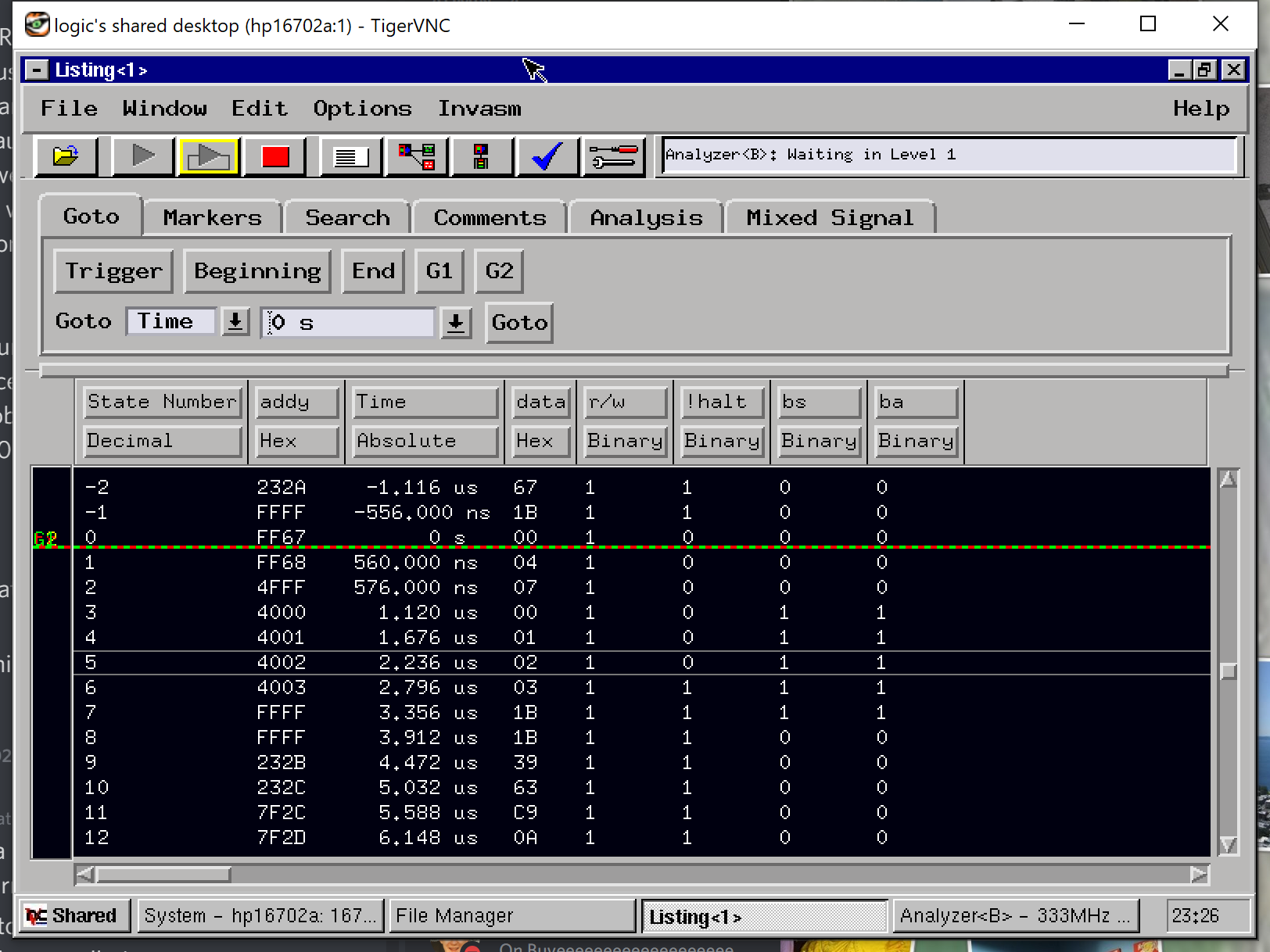
After compiling and downloading the firmware into our test cartridge (which contains 512kB of static RAM), let’s see what we can do. We’ll enable the DMA engine (128 => $ff69), set the external address to $000000, internal address to $4000, and length to $0004:
I’d like to interrupt for a second and express appreciation to David Wood (jbevren on IRC and Discord) for pointing me to the VNC server capabilities on my HP logic analyzer. Starting VNC allows me to capture better screenshots and remotely control the logic analyzer.
In this case, we performed a read from $ff67:68, since the program was written primarily in BASIC with a small EXEC to perform LDD $ff67:rts. We can see the $ff67:68 reads, the HALT line going low after the $ff67 access, the wait for $ff68 access, and then 4 reads from internal memory. Before issuing the DMA transfer, I populated $4000-$400a with the ascending values 0-10, and we see them pulled across the data bus in the trace above.
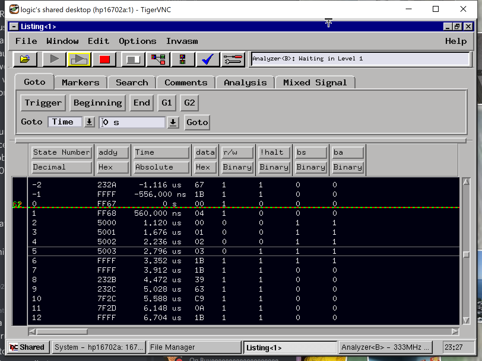
Now, let’s got the other way, transferring those external values back into internal memory at $5000 by turning the DMA engine on, switching transfer direction (129 => $ff69), setting the external address to $000000, setting the internal address to $5000, and keeping the length at $0004:

Again, we see the trigger condition $ff67:68, the HALT condition, and the transfer of our 4 data values from external memory to internal locations, and we see the address incrementing with each transfer. Additional tests show “pinning” an address works as well, which can be useful in the following situations:
- setting memory to a constant value at 1byte/us by pinning the source address at a location that contains that value
- Dumping data to the Orchestra 90 or other CoCoSDC at 1MB/s (Yes, the DMA action works even if both the DMA device and the peripheral are external to the CoCo!)
This invisible memory implementation nicely illustrates the DMA capability available on the TANDY Color Computer 1 and 2. Perhaps this knowledge triggers a fellow enthusiast to develop software that will play to the advantages of this memory expansion option. To that end, all resources associated with this effort have been placed under the Creative Commons Share-Alike 4.0 license and uploaded to a GitHub project repository:
https://github.com/go4retro/PhantomRAM/
If interest warrants, PhantomRAM can be turned into a technology solution, though that is outside the scope of this research effort.
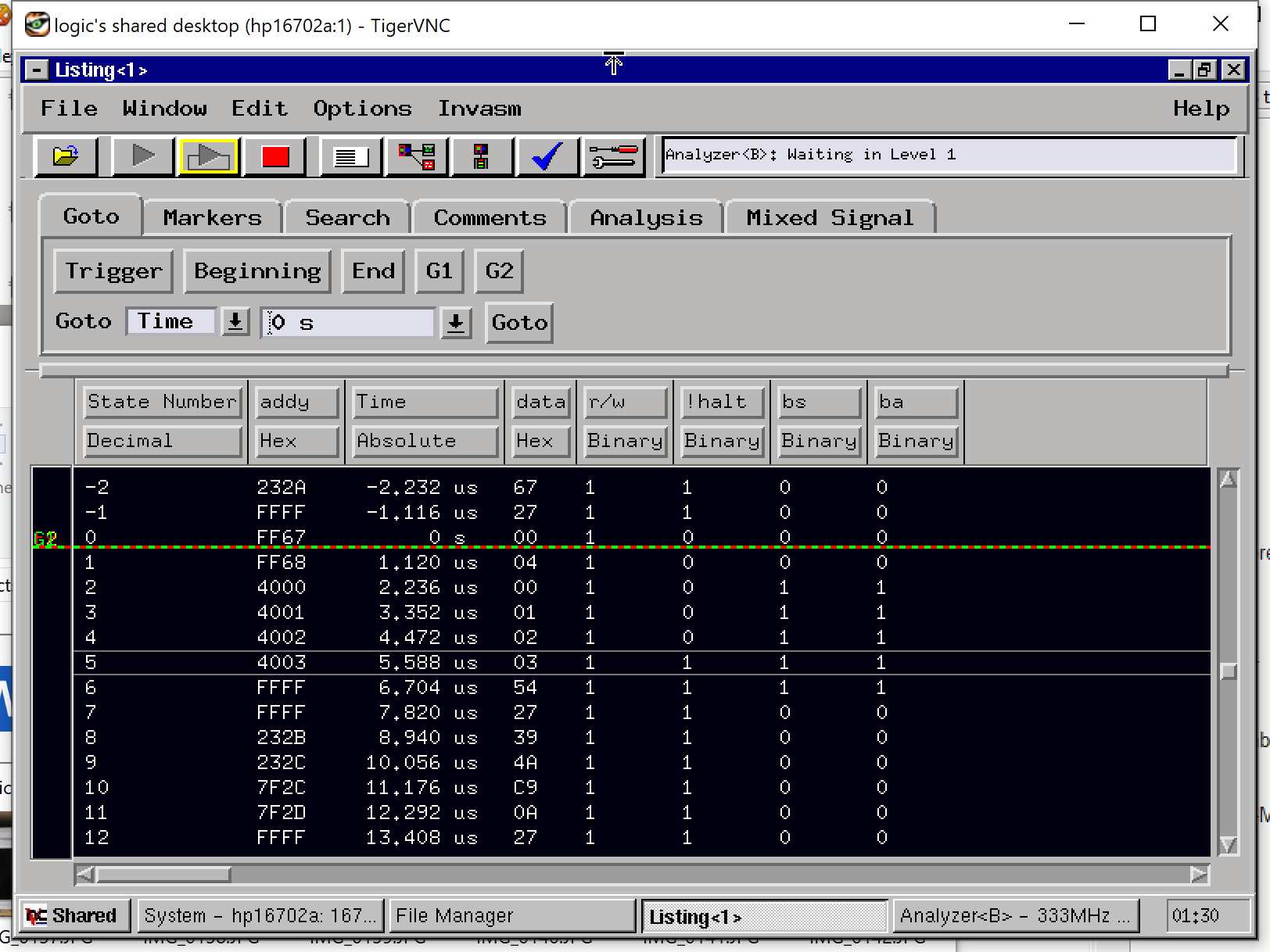
Next time, we turn our attention to the 3rd system in the Color Computer lineup and the challenges it poses concerning DMA functionality. Until next time, I present the following two screen shots (hint: check the timestamps 😊)