Introduction
C=Key bridges the gap between Commodore and PC keyboard operation!
Depending on configuration, C=Key offers VIC-20, C64, C64C, SX64, C128, C128D, and C128DCR owners the ability to either use their CBM keyboard with a PS/2 supported PC, or utilize a PS/2 keyboard on their Commodore machine. In either usage, multiple keyboard mappings are supported, to handle keyboard differences and application preferences. No drivers or programming are required for operation.
Options
C=Key can be purchased in the following configurations:
- PCB Only: Bare circuit board
- PCB + uC: PCB and programmed Atmel ATMEGA162, used for connecting CBM KB to PC (includes uC Crystal and trimming capacitors)
- PCB + uC + Crosspoint Switch: Allows either configuration
- Preconfigured kits for specific CBM models.
Additional options include:
- dual joystick connectors can be added, to allow CBM joystick operation on the PC.
- Any kit can be ordered pre-assembled (please allow additional handling time)
Requirements
- A PS/2 compatible keyboard (USB keyboards with PS/2 converters may not work) with a Mini-DIN6 plug.
- One of the following machines:
- VIC-20, C64, C64C
- SX64
- C128
- C128D/C128DCR
- For the SX64/C128D/C128DCR operation with a PS/2 keyboard, a DB25M to DB25M cable is also required.
Purchase
C=Key models can be purchased at the RETRO Innovations Online Store.
Image Gallery
Technical Details
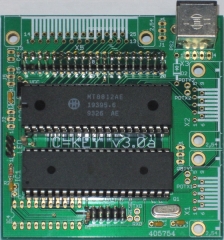
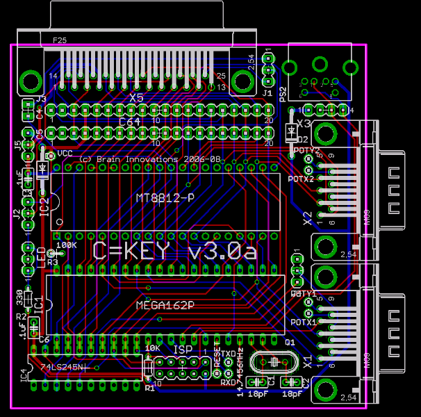
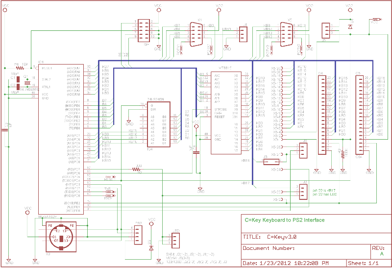
C=Key consists of an Atmel ATMEGA162 microcontroller in DIP format and an optional Mitel/Zarlink MT8812 crosspoint switch. In “host” mode, the system reads data from the PS/2 keyboard and emulates the Commodore switch matrix with the crosspoint switch. In “device” mode, the system scans the Commodore keyboard matrix 60 times a second, converting keypresses into PS/2 compliant scan codes. GPLv2 licensed C firmware source code can be modified to support nearly any matrix-style keyboard configuration.
Firmware features include:
- Multiple key rollover support
- Configurable keyboard matrix scanner supports 1×1 to 16×8 matrices (hardware supports a maximum of 12×8 matrices)
- Single IC solution (for matrix keyboard to PC configuration)
- Key repeat functionality supported and PS/2 keyboard compliant
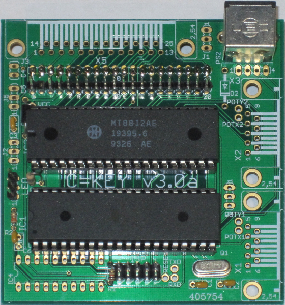
The PCB features include:
- A single PCB for VIC/64/128/SX64
- Support for dual joysticks for emulator use.
- Through hole design makes “do-it-yourself” construction easy.
Support
Bill of Materials
Assembly Details
- Solder all sockets. Remember to align the pin1 notch
- Add X1
- Add C1 and C2 (the 18pF caps)
- Add C6 (.1uF)
- If you have an MT8812 IC, add C3 (.1uF) (the MT8812 is used for PC KB to CBM operation)
- Diodes: Watch the polarity
- If you got a full kit (or a X to/from Y), add both D1 and D2
- If you got a CBM to PC kit, You want to add D2
- PC to CBM, D1
- If you got a C64 or C128 kit, add a 1×3 header to LED and add the 330 (orange/orange/brown) to R2
- Add R1 (10K- Brown/Black/Orange) and R3 (100K – Brown/Black/Yellow)
- For PC KB to VIC/C64
- add 1×20 female header to C4, but under the board (so it will plug into existing KB connector)
- add 1×20 male to C5. (This allows you to continue to use the VIC/64 KB)
- Clip off a 1×20 male header and pull out pin 2 (very important). Install at C5, paying attention to pin 1. (This will allow you to continue to use the existing KB)
- For C128D KB to PC or PC KB to C128D
- Add X5
- Add J1,J2,J3
- For SX64
- Add X5
- Add J1,J2
- For PC KB use
- Add PS2 (PS2 socket)
- Add 2×5 male header to ISP
- Add J5
- Insert IC1 (MEGA162) (WATCH the pin1 notch)
- Insert IC2 (MT8812) if present
- Insert IC4 (‘245) if present. (You should only have this on C128(D) KB to PC models.
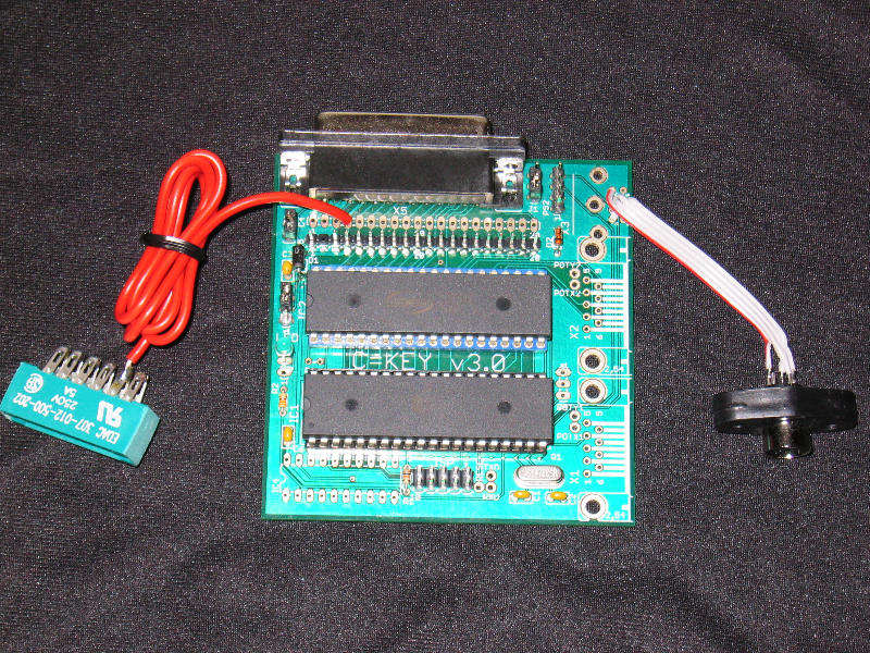
- For CBM to PC usage, you’ll need a mouse cord (I should have made it clearer that is not in the kit). The 1×4 pads by the PS2 connector:
- Power
- Ground
- Data
- Clock
- Configure jumper blocks:
- VIC20/C64/C64C: J5(2-3)
- SX64: J1(1-2), J2(1-2), J5(2-3)
- C128/C128D/C128DCR: J1(2-3), J2(2-3), J3, J5 (2-3)
- For joystick operation: J4(1-2)
Connection Notes:
- On the PC KB to C128, you’ll have to wire the X5 connector to the internal of the C128. I have no other option
- On the PC KB to C128D, you’ll need a gender changer (use a short cable, not a tiny gender bender.)
- The SX64,C128D both use X5, but it won’t fit in a C64 with that installed.
- Final Note: This is still considered a project, not a complete product. I’ll try to help with issues, but it’s still a work in progress.
Operation
The C=Key can operate in a number of configurations, but operates in 1 of 2 modes:
- PS/2 keyboard to CBM mode
- CBM keyboard to PS/2 mode
In either mode, the PS/2 keyboard can send “positional” (Shift 2 sends ‘”‘), or “symbolic (Shift-2 sends ampersand character). As well, there is a C64 mapping and a C128 mapping. Thus, 4 mapping exist for each mode.
Configuration
- On a PC KB, Hold CTRL/ALT and press BS to enter setup mode
- On a C64/C128 KB, It’s CMDR/CTRL and INST/DEL
- LED should blink 10 times
- press 1,2,3,4 for key mappings. C64 Symbolic, Positional, C128 Symbolic, C128 Positional. In the C128 ones, the numpad sends the numpad keys, whereas in C64 modes, the C128 numpad sends C64 top row keypresses
- The LED will blink the number you press
- Press the key combo again to exit config mode.
Downloads
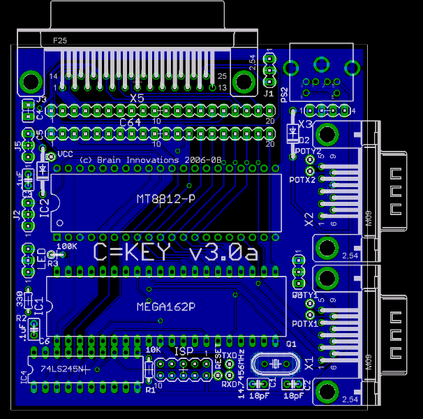
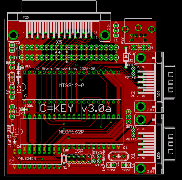
Full source, schematics, and PCB designs are available at the github.com repository.
3 thoughts on “C=Key Keyboard interface”
Comments are closed.