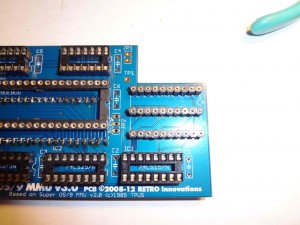
Super OS/9 MMU Construction Details
(These instructions were graciously written by Steven Hirsch)
- Remove CPU board from PET
- Tip unit on its side and remove (2) screws holding top housing to base.
- Place back in upright position and carefully swing top housing back on built-in hinges. Most of the cabling between the CRT and the lower case is not long enough to permit it to lie against the table top, so be sure to support the rear of the CRT housing to avoid damage.
- Unplug all cables from CPU board. Make sure you photograph them beforehand or label them to ensure they are replaced in the correct orientation and position!
- Remove (4) machine screws at the corners and lift CPU out of lower case.
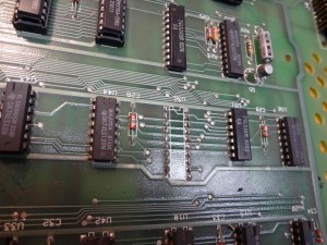
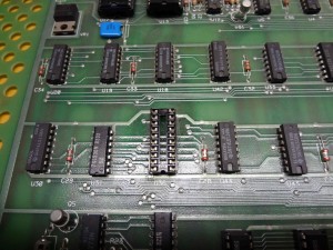
- Remove LS273 chip at U36 and replace with socket
- Carefully pull 6809 CPU from socket and set aside.
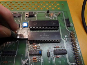
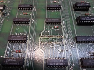
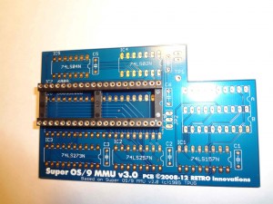
- Align the 40-pin DIP socket as shown and solder to board.
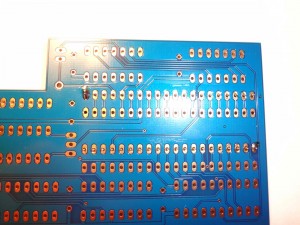
- Mount the 40-pin DIP header to bottom of PCB.
- Check (and double check) the location and pin registration
.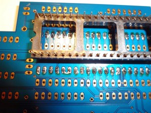
- Make sure that the side of the header with raised areas is facing the PCB.
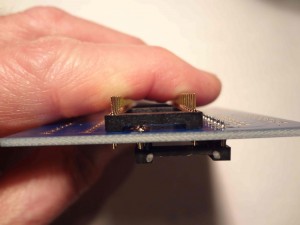
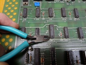
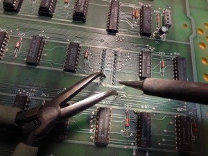
- Clip the center plastic cross-piece from the CPU socket to provide access and solder all header pins from top of board. If you have trouble reaching the end pins under the CPU socket, consider clipping the end pieces as well.
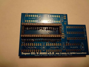
- Check (and double check) the location and pin registration
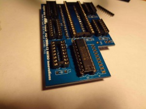
- Mount the A & B header strips and remaining IC sockets.
- Solder jumper pins and bypass caps to the board as shown.
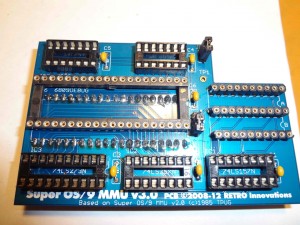
- Carefully align 40-pin machined socket over header pins and press
down until flush.
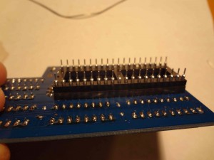
- Remove excess flux from PCB and check carefully for cold solder joints, solder-bridges, etc.
- Insert all ICs into sockets. Double-check part number against screened legend on PCB. Be very careful with alignment of 6809 pins as these parts tend to have very thin and fragile leads.
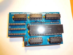
- Carefully align the header extension over the motherboard CPU socket and seat it completely. Check very carefully from all angles to ensure that all pins are properly aligned!
- Plug the 20-pin jumper cable into the socket at U36 and the “A” location on the MMU board.Note: If you have the older 3-board SuperPET, you will need to use
the “B” location.
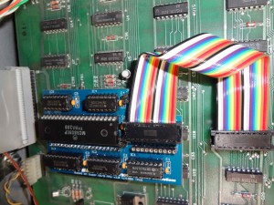
- Fasten the CPU board back into the PET and reconnect all cables. Check carefully to ensure everything is properly registered with the header pins.
- Test the Board (From original TPUG documentation):
- Connect the power cord to the SuperPET
- Toggle the CPU select switch to 6502
- Toggle the RAM read/write protection switch to WRITE
- Turn the power on….
Did the Commodore greeting message appear?
if it did, continue with step 5, else TURN THE POWER OFF, check the CPU/MMU 40 pins socket for bent or improperly connected legs. If the problem cannot be resolved, ask for help. - Toggle the CPU select switch to 6809 mode. Did the Waterloo greeting message appear? if so, continue with step 6 else TURN THE POWER OFF and check for problems as instructed in step 4
- Enter the Waterlo microMonitor and type the following sequence of instructions:
>b0
>f9000.1000 00
>b1

>f9000.1000 01
>b2
>f9000.1000 02
>
>b0
>d9000-
….should dump zeros
>b1
>d9000-
….should dump ones
>b2
>d9000
….should dump twos
