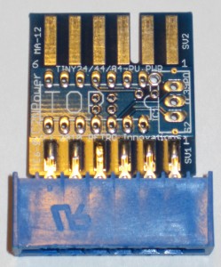
Powering CBM products can prove harder than initially thought. Many manufacturers choose the safe (and professional) route of including a power jack on the product and a plug-in power supply (wall wart). It’s a safe choice, but it carries a double cost. Power supplies tend to be $5.00 or so, and are often bulky and heavy, adding to shipping costs. On the consumer side, there’s a cost in finding another open outlet for the power supply and cable management.
For larger or more power hungry products, it’s a worthwhile tradeoff, but for smaller products, it is more efficient to power the product from the actual machine. Even today, USB devices can obtain power from the host computer, as long as they do not consume more than 100mA of power. Above that, and they require an external power source. Thus, for smaller CBM projects, it’s tempting to draw power from the console itself. On the Commodore VIC-20, C64, C64C, and C128, power can be sipped from the user port, cassette port, and/or expansion port, as well as from the joystick ports.
Over time, the cassette port has become the preferred port for power draw. Mainly, it’s rarely used. The joystick ports are smallest and probably cheapest to interface, but they are heavily used and can be prone to accidental disconnection. Still, the cassette port can prove challenging for interfacing in 2010. Most importantly, the .156″ 6 position connector is hard to source nowadays.
When I started offering products, I chose the cassette port because it offered a way to reduce prices for consumers, and the products used minimal power, making the port an ideal power source. With that decided, I simply needed to source the cassette port connectors and start selling products.
Oh, how I wish it were that easy! To understand the challenge, let me relate a bit of technical information. The standard PET/CBM cassette connector is a male 6/12 .156″ edge connector. For obvious reasons, Commodore created the male portion on the compute rmotherboard, as it was cheap (it requires no connector, just etching the connector conductive “fingers” onto the motherboard). To interface, one needs the female portion, which comes in 2 basic styles. One is designed for chassis (enclosure) mounting and contains 2 tabs on each end, each with a hole in them. They are called “mounting tabs”. The idea is to cut a hole in the case, mount the connector using the “tabs” and the holes, and then use the connector. The other foregoes the “tabs”. Since the “tabless” version is less useful (most use cases require a mounting option), it’s harder to source. Therefore, I initially obtained the more plentiful “tabbed” version of the cassette port connector for my power needs.
After I’d sold a number of units with the cassette port power connector, I noticed two things:
- The installed connector was very hard to remove from the C64 or C128, as the cassette port on all CBM units is recessed into the case. Although I’d already know about the issue of removing the connector in general, that issue and this one didn’t concern me greatly because I surmised the connector would not often be removed.
- The tabs prevented C128DCR usage. Commodore evidently reduced the width of the cassette port opening in the C128DCR case, making the tabbed connector too wide for entry. Although this was not a major issue (removing the tabs addresses the concern), it caught some folks off-guard and provided fodder for reviews and such.
Still, I had 150 of the tabbed connectors and no source for the non-tabbed connectors, so I pushed forward. Along the way, though, I both used up my stock of connectors and also managed to find a source for the more elusive non-tabbed connector.
With experience in hand, I decided to rework the power connection option for the product line. In addition to the previous issues, a few folks has lamented the lack of a cassette port “pass through”. Thus, I decided to fix all of the issues at once. The removal issues and the passthrough request could easily be solved by adding a small PCB to the connector (something to grab onto), and etching a cassette port male connector on the opposite end of the PCB. The C128DCR concerns required sourcing a non-tabbed connector. The resulting board would like similar to printer interface cassette port power adapters of the era. But it seemed a waste to create a PCB just to bring the signals out for passthrough usage.
Never one to ignore an opportunity, I decided to add some value to the power connector. In contemporary PCB design, it’s a fact that you’re paying for the area of PCB, rarely anything else. By creatively laying out the PCB, I managed to find space for a DIP-14 socket and a single pole switch. TO use the DIP socket, I mapped out the pin configuration for a small Atmel AVR microcontroller, the ATMEGA24/44/84. The cassette port signals all route to the AVR, as does the switch.
Mind you, I have no immediate plans to create a product using the uC onboard the connector. Thus, the uC is unpopulated, but one can easily add the socket and the controller. Nonetheless, I’m interested in idea for usage, and eager to see if hobbyists come up with independent ideas for usage.
One thought on “Project Within A Project”
Comments are closed.