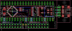
Based on forum feedback, I have refined the Micro ZoomFloppy design for fit and function. Many people comments on the non-optimal placement of the USB connector. I noticed that as well, but the original design goal was to provide maximum installation flexibility. Placing the USB connector on board eliminated the need to mount a USB jack on the case. Installers could simply connector a suitable cable to the connector and let the cable ass through the case at some convenient point. However, the idea was abandoned when others pointed out that the placement of the connector would interfere with other ICs on the drive PCB in many drive configurations. The new design places the USB connector on a separate PCB assembly, which connects to the main board via a 4 wire cable.
The 1541 parallel cable connector remains on the layout. Even when the board is populated, the parallel connector can be used by another ZoomFloppy device for parallel operations.
Other changes were smaller:
- Jumpers were added to bridge any signals that were not passed through the connectors. This allows the design to be used without the uC and related circuitry as a simple parallel cable connector board.
- The 1571 parallel cable connector was added to the design. Again, this is useful when the board is unpopulated and would then be installed in the 6526 socket on a 1571 drive. Unlike the 1541 parallel connector, this connector does not serve a function when installed in the 1571 6522 socket.
Now, the software must be modified and tested for correct operation before the PCB can be assembled.