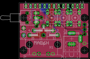
Due to some changes in the PCB houses my assembler uses, and cost issues with the DIN6 connector for the uIEC/SD daughtercard, it’s actually cheaper to create a new PCB design than to use the old one. To that end, I have slightly modified the design to include a power supply connector and a switch to disable the RESET line (in case you wanted the device to stay in a subdirectory across reboots of the computer). To stay on delivery targets, I need to send this off to the assembly house this week, but I am interested in comments on the changes and any others that might be possible. Before people ask, I attempted to add a second IEC connector, but then the IEC connectors must be positions to face the side, and the board ends up larger than the uIEC/SD itself.
I like, though it’d still be nice to have one with a passthrough UIC connector. Perhaps it would fit if a mini-din and then adapter thing was setup?
Oh one more thing, what about a push’on’off instead of a toggle switch. That is of course unless there exists an off-the-shelf case this fits in.