New(ish) Project: VIC-MIDI

VIC-MIDI Prototype
VIC-MIDI Prototype

This project had its start in a late 2009 discussion between Leif Bloomquist, a Canadian Commodore enthusiast and musician, and myself.  Leif had been playing with a hand-built 6850-based VIC-20 MIDI cartridge designed off a 1980’s era Maplin “Electronics” article, and wondered if a production run could be arranged.  I took a look at the design, and noted that the 6850 UART would be hard to source.  I suggested some design changes to bring costs down, and plans were made to refine the design.

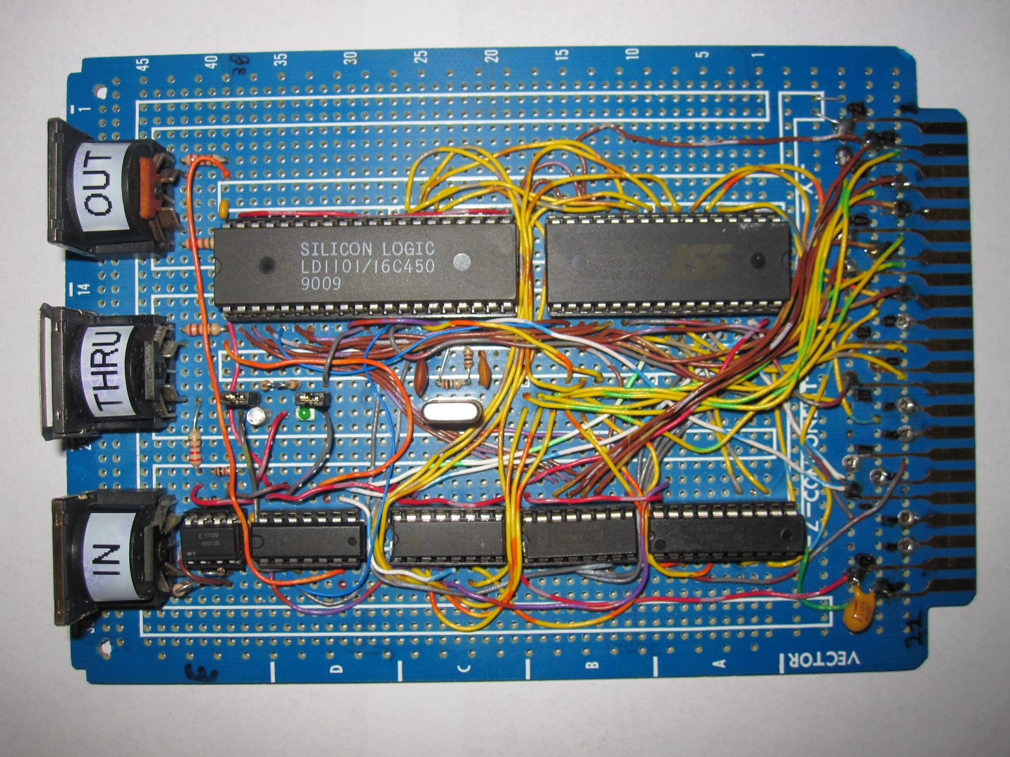
To further the design, I wired up a newer UART (16450-based) to a daughtercard that could plug into the 6850 socket on the original board.  That allowed Leif to refine the software, and provide out the redesign.  Once that was done and successful, we discussed a final production version.  Changes included offering a built-in user-flashable ROM function.

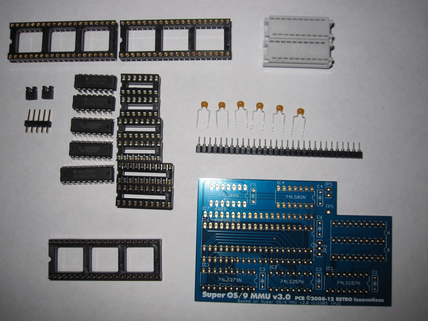
That brings us up to late 2012.  I purchased the parts for a completely new prototype board, but could not get it assembled by World of Commodore, so I brought the parts to the show and hired the assembly done.

Well, the assembly resource took longer than expected to finish the construction, but I did receive this same exact board mid-Feburary 2013.  I fixed a few small design issues, only to discover the board expansion port was wired 100% backwards.  Commodore, for reasons known to them only, named the pins on the VIC-20 expansion port in reverse from the industry standard.  Since the prototype PCB pins were named according to the standard, every one would need modification.

I packaged up the board and sent it back to the assembler, but I must have messed up the address, as it did not arrive in a timely fashion.  Since I had shipped it from the Post Office directly, I didn’t get tracking information, and thus had no idea of its location.  After a few weeks, I resigned myself to the loss of the unit, and started gathering parts for a second unit to be shipped via trackable shipment to the assembler.  As it turns out, the assembler and I were both planning to attend the 2013 Midwest Gaming Classic in WI, so I made plans to transfer a new set of parts during the show.

No sooner than the show ended and parts were transferred, the original package showed up at my office, undeliverable.  I quickly saw the addressing issue, created a new trackable label with the correct address, and sent it on its way.  Which brings us to last week, when the unit arrived, after the rewiring effort.

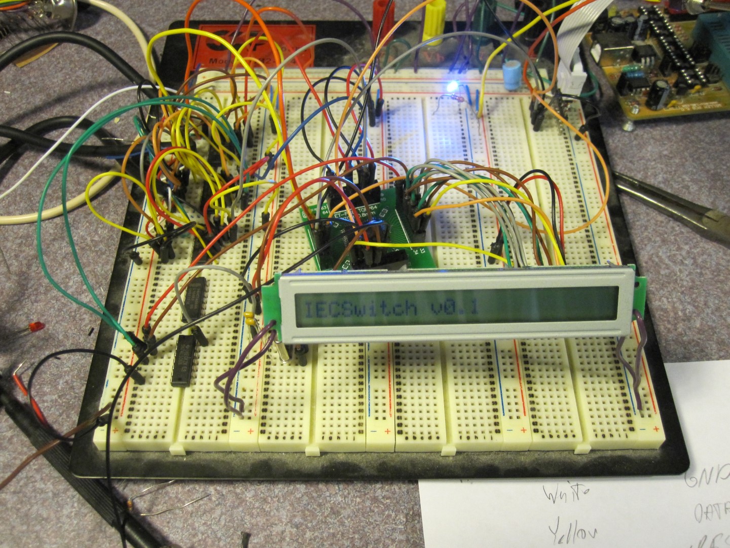
After all of that effort, I could now begin the potentially laborious task of debugging a “paper design”.  I had designed the entire unit on paper, but had not previously proven out any of the elements on a breadboard.  Though the original UART design was working on Leif’s PCB, the new design was marked different, owing to the additional decoding logic needed for the FLASH ROM.  As such, it was almost a completely new design.   I’m not sure if credit is deserved and who deserves it, but the UART and FLASH ROM read access worked out of the box.  Bank selection for the FLASH ROM did not work, but that’s a minor issue.

And, we’re almost to the point of creating a VIC-20 MIDI production design.

New Project: IECSwitch

IECSwitch v0.1
IECSwitch v0.1

I can’t claim a significant amount of creativity, but over the past few years, two folks have dropped off “VIC-Switch”-like devices in hopes that I could reverse engineer them.  THese are devices used back in the day (typically in schools) to share a single disk drive or disk and printer with up to 8 computers. I long ago drew up schematics of the existing designs, but wanted to freshen up the solution instead of just creating a replica.

Well, as it goes, finding time takes time, but I decided to try my hand at a new design, and here is the current result.  It’s not much at present, though I can enable/disable IEC ports, and “hold” the 64 from timing out the bus request.  Yes, that’s an LCD there.  I found a great price on them, and I think that’ll be in the final design.  It’s only marginally cheaper than a 7 segment LED or two, and much more interactive then a few LEDs.

It’s been awhile since I developed firmware, and this gave me a chance to clean the cobwebs off my programming skills.

Coming Soon: SuperOS/9 MMU Kit

SuperPET OS/9 MMU
SuperPET OS/9 MMU

In the “another project that has been long in gestation” category comes a niche offering for those with Commodore SuperPET machines and a desire to run the OS/9 operating system.  OS/9, a multi-tasking, multiuser, realtime OS with UNIX-like qualities, was popular in the 1980’s and ran on machines with the Motorola 6809.  In addition to the small TRS80 Color Computer, the SuperPET includes a 6809, but the standard memory map of the SuperPET does not lend itself to OS/9 operation.  That is where this little board comes in.  Installation does not affect normal SuperPET operation, but extends it with OS/9 compatibility.

The SuperPET, a variant of the Commodore 8032 that included additional boards designed by the University of Waterloo, did not sell well, as far as I can tell, and limited (though not ultra-rare) numbers exist.  Still, for those lucky enough to own one, OS/9 can truly turn the SP9000 (another name for the SuperPET) into the MicroMainFrame (another name for the SuperPET).

The project has been gestating since 2008 in some fashion.  Late that year, TPUG member Golan Klinger asked if I could reproduce the SuperPET MMU board, which TPUG members created in 1985. for a possible club fundraising activity.  I dutifully created a new layout of the design, and awaited next steps.  Around the same time, Mike Naberezny (of 6502.org fame) started discussing the board, and we eventually compared notes.  Over time, it became evident that TPUG was not going to pursue offering the unit for sale, and Mike performed a significant amount of legwork obtaining permission to replicate the software from Radisys (who purchased the OS/9 rights) and permission from TPUG leadership to offer the PCB.  Thus, the majority of credit for this offering goes to Mike, who has a web site devoted to this impressive little board.  I’ll put one in due time, but it won’t provide any more detail than Mike’s.  I should also give a shout out to Steve Gray, who helped with information and PCB scans.

Currently, due to the low volumes, the unit will be available in kit form only for approximately $30.00.  Thus, break out your soldering iron and a weekend of time to add this capability to your SuperPET!

Seeing (EasyFlash 3) Red!

EasyFlash 3 Finished Unit

The difference between a project and a product often boils down to looks. Along with a professionally designed and manufactured circuit board, a proper enclosure completes the package.

Thought we have long offered a un-machined cartridge case with 64NIC+ Ethernet cartridges, we had resisted the thought of milling cartridge cases.  In the case of the 64NIC+, the Ethernet jack machining is tough and prone to error.  A proper CNC milling machine is required to efficiently handle such a design.  However, the EasyFlash 3 did not require so complex a solution to correctly machine a suitable cartridge enclosure.  Some simple jigs on the drill press and creative use of drill bits ably substituted for a CNC mill.  As a result, EasyFlash 3 arrives in an optional fully machined enclosure.

The red color choice was somewhat arbitrary, as we have clear enclosures.  Still, translucent red and the red LED on the unit seemed to fit well together.  I hope you agree.

The EasyFlash 3 is now available in our online store.


X Pander-3 VIC Progress

X-Pander 3 VIC Assembled PCB

The wait is almost over for VIC Expansion enthusiasts.  After a significant delay, X-Pander 3 VIC units are nearing the end of assembly.  As the photo shows, only the IO2/IO3 SWAP jumpers are left to assemble.  We hope to add this to the store by the end of the week.

Given the width of VIC-20 cartridges, the finished units will have the switches located underneath the board, but will otherwise look identical.

As the picture suggests, the unit shares the same basic layout and operation as the X-Pander 64, but adds additional switches to control BLK and RAM lines.

uIEC/SD Daughtercard v3.2 In Production

uIEC/SD Daughtercard v3.2
uIEC/SD Daughtercard v3.2 (side view)

While replenishing stock of uIEC/SD daughtercards, I decided to improve the design a bit.  Hopefully, this version will eliminate the need to offer the original daughtercard option.

Features:

  • Buttons now on side of unit, for easier access.  Buttons can now be used on C128D/C128DCR when installed.
  • Operational Mini-USB connector.  If desired, power with a small Mini-USB phone charger
  • Complete 7805-based linear regulator section available for hobbyists.  Parts are not present on the board, but should be trivial to source (2 caps and an LM7805)
  • Oversized holes at front of board to allow PCB standoff usage.  When powered via MiniUSB, standoffs can be used to level the PCB.

The new daughtercard works with all uIEC/SD versions (3.0,3.1, and 3.2).  Stock will be arriving soon.  Production boards will have sorter switch posts, for some reason, I accidentally ordered taller ones for the prototype.

C2N Power! v2.0 Hardware Ready

C2N Power! v2 top
C2N Power! v2 top
C2N Power! v2 bottom

Well, C2N Power! v2 is manufactured and the first few units are assembled,  Hopefully, this weekend I can verify electrical operation and then I’m hoping to ship a few of them to developers for software creation.  The offer is still open for assembly programmers who want a small weekend challenge.

The unit is shown assembled for Real Time Clock operation, with a Maxim DS1307+ installed under the unit, with I2C pullup resistors and the MOTOR line conversion transistor in place.  On top, a lone 3V3 Lithium battery powers the RTC when CBM power is absent.

EasyFlash 3 Manufacturing Progress

EasyFlash 3
EasyFlash 3

It’s taken a while, but EasyFlash 3 units are nearing completion.  All SMT components are installed, and the LED, switches, and jumper pins are all that remain.  I am hoping the assembly house can ship this week so I can deliver units starting next week.

I’ve asked that the first 100 units be shipped before the second 100 are completed.

Since many people have ordered cases, it looks like I have some holes to drill before shipping 🙂

IEEE Adapter

IEEE Adapter PCB
IEEE Adapter PCB

For reasons I can only guess, Commodore created it’s IEEE-488 cables in two forms.  The first was a standard Centronics 24 to Centronics 24 cable, with each end of the cable offering a passthrough connector (male on the top, female on the bottom).  This cable could be used to connect any CBM IEEE-488 peripheral to any other CBM IEEE-488 peripheral, creating a chain of peripherals through a single cable.  However, the second, and more important cable was the one that connected the PET or CBM machine to the first peripheral of the chain.  And, on one end of this cable, Commodore specified a .156 12/24 female edge connector.

Ordinarily, I’d guess the reason was cost reduction, and that might indeed be the truth, but IEEE-488 cables in general were not cheap, and creating a specific non-standard cable that only Commodore would use seems contrary to a cost reduction move.  My next thought was “vendor lock-in”, but if that were the reason, why bother with standard cables anywhere?

There are other theories, of course, and I don’t spend much time considering why these things occur.  However, such a design decision makes a real impact today, more than 30 years since the cable debuted.  Namely, the non-standard cables are hard to find, and no one produces them anymore (standard IEEE-488 cables are still produced in significant quantities).  Since each PET/CBM machine needs exactly one of these cables, they are somewhat important.

One can always cut a standard cable and wire up a 12/24 connector, but I recently saw a neat idea on a classic computer mailing list that concisely solves the problem: An IEEE-488 connector adapter.  The adapter is simplistic to an extreme.  One end contains a 12/24 .156″ connector, while the other contains a standard Centronics-24 connector.  Coupled with a standard cable, the search for this elusive connection option can be over.

The design seems so simplistic, I’m wondering if there is something else that can be added to the design before I send it off for production.  Comments are welcome.

C2N Power!

C2N Power! PCB
C2N Power! PCB

Given a need to order more C2NPower cassette port power adapters, RETRO Innovations has revamped and expanded the functionality of this tiny product.  In addition to providing a tap for 5VDC for powered peripherals and a layout that includes holes for the Atmel ATTINY24/44/84 AVR microcontrollers, the new design also includes support for the MAXIM DS1307+ (and compatibles) Real Time Clock and the 24CXXXX line of serial EEPROMs.

Before we roll this new design into production, we’re looking for a couple of proficient assembly language developers who could help us develop some functions for reading and writing the time to the RTC and reading/writing data to the EEPROM.  The protocol is I2C, using the MOTOR and WRITE lines for SCK and SDA, respectively.  The only nuance is that MOTOR line is inverted.  We’re hoping some folks would like to compose a bit of code in exchange for a free  C2N Power! unit (with EEPROM and RTC supported).  Ideally, we’d like to create some common 6502 code for the basic routines that can be used on the PET, 40XX, 80XX, VIC, 64, and C128 machines with only minor variations among platforms.

Thus, if you or someone you know could help, please let us know via our contact page. Feel free to repost as appropriate.